Detonation Pickup Basics
By Chad Michaelis at Vertex Electronics Inc.
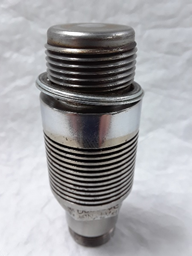
The detonation pickup has been around since 1946, when it was introduced by Phillips Petroleum Company (Figure 1). Different forms of bouncing pin technology were utilized prior to the introduction of the detonation pickup. The detonation pickup has changed little since its introduction and was designed to mimic the signal response of the bouncing pin system to help ease the transition away from the bouncing pin (Waukesha, Form 847, p.43, 2003). The pickup has been manufactured by several companies, including Phillips Petroleum, Waukesha, Western Electric and Lane Wells. Pickups have been manufactured to common dimensions and response characteristics to knock events. A pickup is composed of several different parts and some of the major components are the pickup face, magnetic body, magnetostrictive rod, coupling coil and electric terminals (Figure 2).
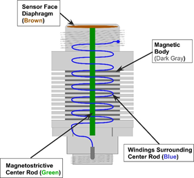
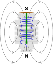
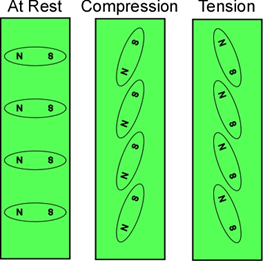
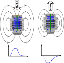
The pickup face is directly in contact with the changing pressure media inside the combustion chamber of the test engine. The magnetic body creates a standing magnetic field (Figure 3). The pressure forces the magnetostrictive rod to compress. The rod compression then forces micro magnetic poles to realign such that the overall magnetic field varies (Figure 4). If a coil of wire is placed inside a changing magnetic field, a voltage will be generated in the coil wire. The changing pressure in the combustion chamber induces the pickup to output an electrical signal that is representative of the rate of change in pressure (Figure 5).
The detonation pickup has stood the test of time and the design has proven to be a robust answer to a harsh and complex application. Vertex Electronics has developed the latest pickup testing equipment and processes to help the industry quantify characteristics of detonation pickups. For more information on Vertex’s offerings, please visit the Vertex Electronics Website.
Copyright © 2019 Vertex Electronics Inc.
Tags: Vertex Electronics
 EngineBuzz